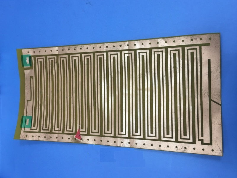
With the development of high-end, miniaturized electronic products such as mobile phones, notebook computers and PDAs, the demand for flexible boards is increasing, and PCB manufacturers are accelerating the development of thinner, lighter and denser.
1.Single-layer FPC
It has a layer of chemically etched conductive pattern. The conductive pattern layer on the surface of the flexible insulating substrate is a rolled copper foil. Single-layer FPC can be divided into the following four categories:
1-1.Single-sided connection without cover
The wire pattern is on an insulating substrate, and there is no covering layer on the surface of the wire. The interconnection is realized by soldering, fusion welding or pressure welding, which is commonly used in early telephones.
1-2.Single-sided connection with cover
Compared with the previous category, there is only one more cover layer on the surface of the wire. The pads need to be exposed when covering, it is simple to not cover the end area. It is one of the most widely used single-sided flexible PCBs.
2.Double-sided FPC
Double-sided FPC has a layer of conductive patterns made on each side of the insulating base film, which increases the wiring density per unit area. The metallization holes connect the two sides of the insulating material to form a conductive path to meet the design and use functions of flexibility. The cover film protects single and double-sided wires and indicates where the component is placed.
2-1.Double-sided connection without cover
The land interface can be connected on the front and back of the wire. A via hole is opened in the insulating substrate at the pad. This via hole can be punched, etched or other mechanical methods at the desired position of the insulating substrate. to make.
2-2.Double-sided connection with overlay
The former type is different in that there is a cover layer on the surface, and the cover layer has via holes, allowing both sides to be terminated, and still maintain the cover layer, which is made of two layers of insulating material and a metal conductor.
3.Multi-layer FPC
Multi-layer FPC is a method of laminating single or double-sided flexible circuits with 3 or more layers, forming metallized holes by drilling collar L and electroplating, and forming conductive paths between different layers. This eliminates the need for complicated welding processes. Multi-layer circuits have huge functional differences in terms of higher reliability, better thermal conductivity, and easier assembly performance.
The advantage is that the substrate film is lightweight and has excellent electrical characteristics, such as a low dielectric constant. A multi-layer flexible PCB made of polyimide film as a substrate is about 1/3 lighter than a rigid epoxy glass cloth mult-ilayer PCB. Flexible, most of these products do not require flexibility. Multi-layer FPC can be further divided into the following types:
3-1.Finished flexible insulation substrate
This type is manufactured on a flexible insulating substrate, and its finished product is specified to be flexible. This structure usually glues the two side ends of many single-sided or double-sided microstrip flexible PCBs together, but the central parts are not bonded together, so it is highly flexible. In order to have a high degree of flexibility, a thin, suitable coating, such as polyimide, can be used on the wire layer instead of a thicker overlay.
3-2.Finished insulating base material
This type is manufactured on a flexible insulating substrate, and the finished product is not specified to be flexible. This type of multi-layer FPC is made of a flexible insulating material, such as a polyimide film, laminated into a multi-layer board, which loses its inherent flexibility after lamination.
For more question or technology issues about flexible PCBs, please contact us via service@wellerpcb.


